


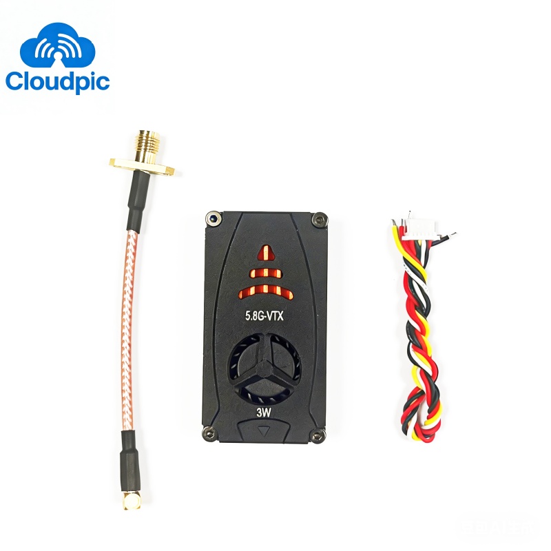


CP503T 5.8G 3W transmitter


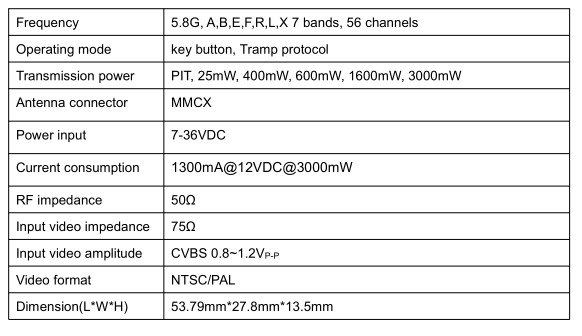
1. General Specifications
Parameter | Specification |
Frequency | 1.5G 8CH (1380-1520Mhz) |
Input Voltage | DC 12-32V, supports 3-7S battery input |
Output Power | 25mW/800mW/2000mW/5000mW @12V/2500mA |
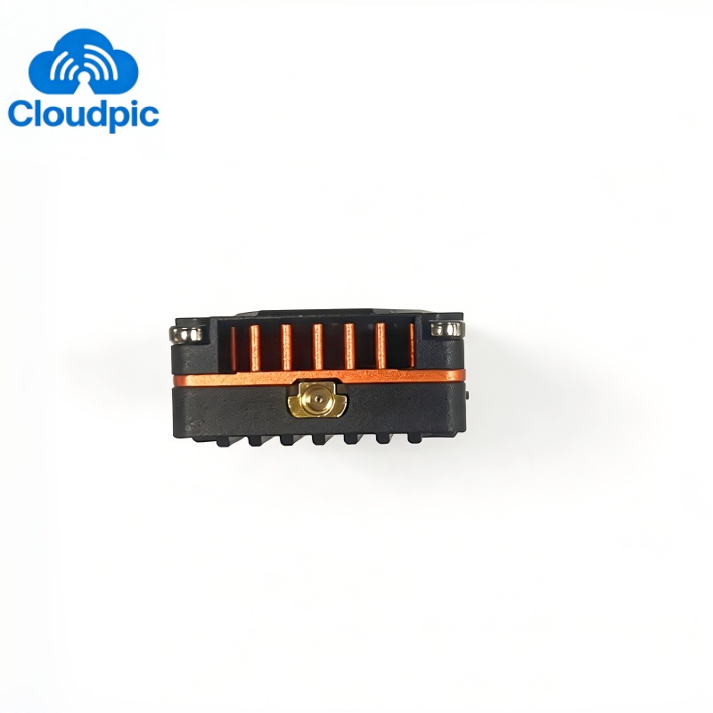
Antenna Interface | SMA female inner hole |
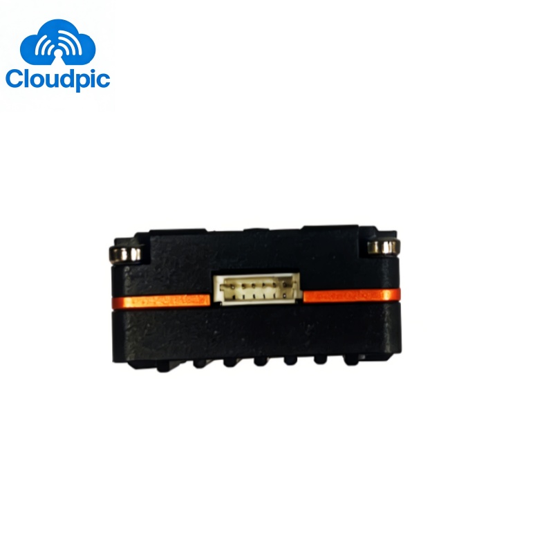
Input Interface | GH1.25 4P + SH2.0 2P |
Mounting Holes | 25×25/Φ2mm, 30.5×30.5/Φ2mm |
Video Transmission Protocol | IRC Tramp |
Weight | 68g |
Dimension | 69×36×22.5mm |
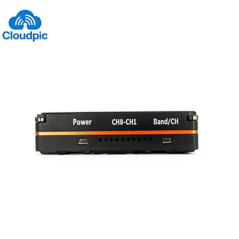
2. Button Operation
2.1 POWER Button (Green Light Indication)
Short press to switch power; the number of blinks indicates the current power:
· 1 blink = 25mW
· 2 blinks = 800mW
· 3 blinks = 2000mW
· 4 blinks = 5000mWLong press for 2s to switch to PIT mode (steady green light indicates PIT mode is activated).
2.2 Band/CH Button
Red Light (Frequency Band Indication)
Long press for 2s to switch frequency band; the number of blinks indicates the current band:
· 1 blink = Band A
· 2 blinks = Band B
Blue Light (Frequency Channel Indication)
Short press to switch channels, cycling through CH1 to CH8 in turn.
3. RF Transmission Frequency Table (MHz)
Frequency Band | CH1 | CH2 | CH3 | CH4 | CH5 | CH6 | CH7 | CH8 |
BAND_A | 1380 | 1400 | 1420 | 1440 | 1460 | 1480 | 1500 | 1520 |
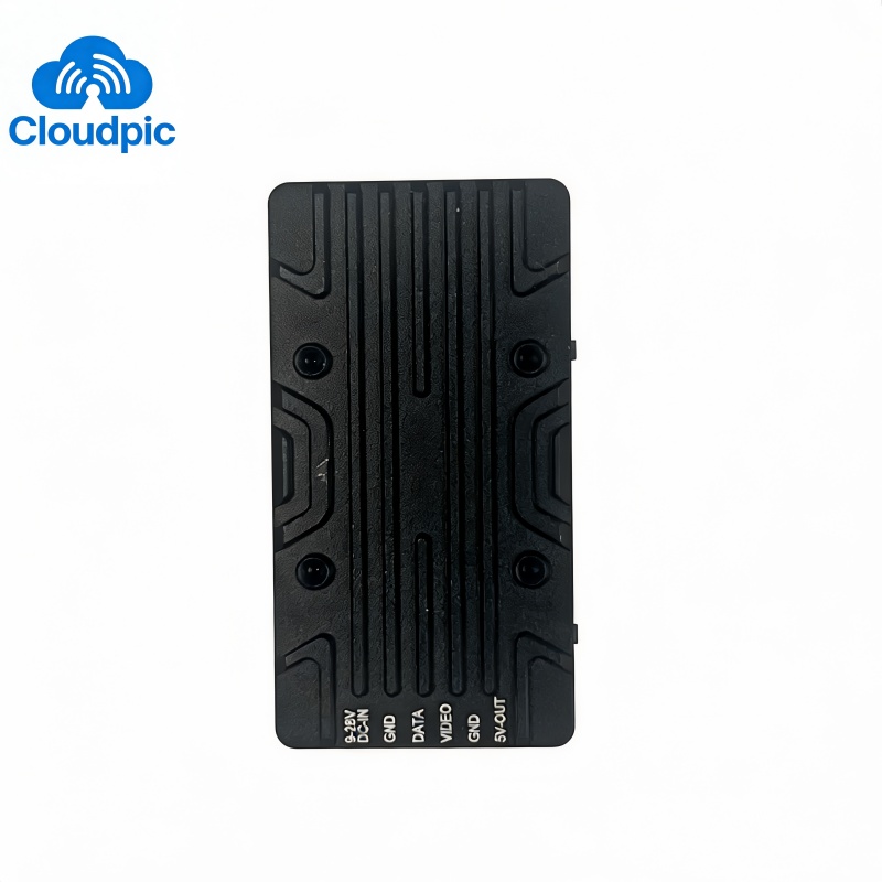
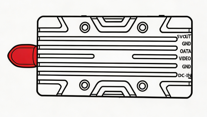
3. Wiring Definition
12-36V, GND, RX, VIDEO, GND, 5V-OUT |
4. Warnings & Notes
① Mandatory Antenna Installation: The antenna must be installed before power-on.
② Heat Dissipation Requirement: The video transmitter may be damaged if there is insufficient heat dissipation during use.
③ Installation Requirement: Leave sufficient space around the module during installation to ensure air circulation and effective heat dissipation. Overheating will cause power reduction or even complete transmission shutdown.

